
HSSE Form B Machine Taps – Through Holes
HSSE Form B machine taps cut metric threads in through holes up to 4 × D. Straight flutes and a spiral point push chips forward in the cutting direction, preventing them from accumulating in the finished thread.
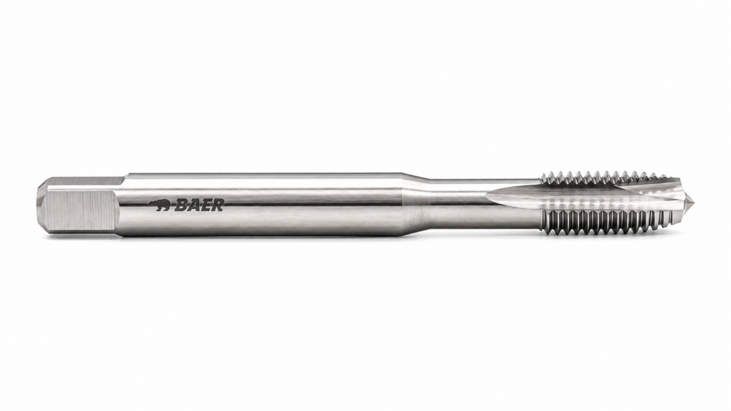
Main characteristics
- Standard
- DIN 371 or DIN 376, depending on size and shank
- Thread
- M ISO metric coarse thread to DIN 13, ISO2 / 6H tolerance
- Flute geometry
- Straight flutes, Form B with spiral point
- Chamfer
- 4–5 threads; chips travel forward
- Tool material
- HSSE cobalt high-speed steel
- Surface
- Bright, uncoated
- Hole type
- Through hole up to 4 × D
- Cutting direction
- Right hand
- Coolant
- External cooling and lubrication
Applications
For machine cutting of internal metric threads in through holes. The Form B spiral point guides chips ahead of the tool and away from the finished thread.
- unalloyed and low-alloy steels,
- easily machinable materials up to 900 N/mm²,
- production, maintenance and industrial workshops,
- through holes up to the recommended depth of 4 × D.
Selecting the correct version
Select the nominal thread and pitch first. For duplicated thread sizes, check the standard and shank diameter: M3 to M10 are available both with a reinforced DIN 371 shank and a reduced DIN 376 shank.
DIN 371 and DIN 376 – what the standards define
DIN 371 and DIN 376 are dimensional standards for machine taps. They define overall length, thread length, shank diameter and square size. They do not by themselves define the hole type or workpiece material.
| Standard | Typical use | Shank design | Typical range |
|---|---|---|---|
| DIN 371 | smaller machine taps | reinforced shank | smaller threads |
| DIN 376 | larger machine taps and reduced-shank versions | shank adapted to the thread diameter | larger threads; in this range also M3–M10 with a reduced shank |
STANDARD = dimensional design of the tool
GEOMETRY = straight flutes, spiral point and Form B
APPLICATION = through or blind hole according to geometry
WORKPIECE MATERIAL = according to geometry, tool material, coating and manufacturer recommendation
Dimensions and item numbers
| Item No. | Standard | Thread | Pitch | Tap drill | Overall length | Thread length | Shank | Square |
|---|---|---|---|---|---|---|---|---|
| mm | mm | mm | mm | mm | mm | |||
| 110401001 | DIN 371 | M2 × 0.4 | 0.4 | 1.6 | 45 | 8 | 2.8 | 2.1 |
| 110401002 | DIN 371 | M2.5 × 0.45 | 0.45 | 2.05 | 50 | 9 | 2.8 | 2.1 |
| 110401003 | DIN 371 | M3 × 0.5 | 0.5 | 2.5 | 56 | 11 | 3.5 | 2.7 |
| 110401004 | DIN 371 | M3.5 × 0.6 | 0.6 | 2.9 | 56 | 13 | 4 | 3 |
| 110401005 | DIN 371 | M4 × 0.7 | 0.7 | 3.3 | 63 | 13 | 4.5 | 3.4 |
| 110401006 | DIN 371 | M5 × 0.8 | 0.8 | 4.2 | 70 | 16 | 6 | 4.9 |
| 110401007 | DIN 371 | M6 × 1.0 | 1.0 | 5 | 80 | 19 | 6 | 4.9 |
| 110401008 | DIN 371 | M7 × 1.0 | 1.0 | 6 | 80 | 19 | 7 | 5.5 |
| 110401009 | DIN 371 | M8 × 1.25 | 1.25 | 6.8 | 90 | 22 | 8 | 6.2 |
| 110401010 | DIN 371 | M10 × 1.5 | 1.5 | 8.5 | 100 | 24 | 10 | 8 |
| 110401011 | DIN 376 | M3 × 0.5 | 0.5 | 2.5 | 56 | 11 | 2.2 | 2.1 |
| 110401012 | DIN 376 | M4 × 0.7 | 0.7 | 3.3 | 63 | 13 | 2.8 | 2.1 |
| 110401013 | DIN 376 | M5 × 0.8 | 0.8 | 4.2 | 70 | 16 | 3.5 | 2.7 |
| 110401014 | DIN 376 | M6 × 1.0 | 1.0 | 5 | 80 | 19 | 4.5 | 3.4 |
| 110401015 | DIN 376 | M8 × 1.25 | 1.25 | 6.8 | 90 | 22 | 6 | 4.9 |
| 110401016 | DIN 376 | M10 × 1.5 | 1.5 | 8.5 | 100 | 24 | 7 | 5.5 |
| 110401017 | DIN 376 | M12 × 1.75 | 1.75 | 10.2 | 110 | 29 | 9 | 7 |
| 110401018 | DIN 376 | M14 × 2.0 | 2.0 | 12 | 110 | 30 | 11 | 9 |
| 110401019 | DIN 376 | M16 × 2.0 | 2.0 | 14 | 110 | 32 | 12 | 9 |
| 110401020 | DIN 376 | M18 × 2.5 | 2.5 | 15.5 | 125 | 34 | 14 | 11 |
| 110401021 | DIN 376 | M20 × 2.5 | 2.5 | 17.5 | 140 | 34 | 16 | 12 |
| 110401022 | DIN 376 | M22 × 2.5 | 2.5 | 19.5 | 140 | 34 | 18 | 14.5 |
| 110401023 | DIN 376 | M24 × 3.0 | 3.0 | 21 | 160 | 38 | 18 | 14.5 |
| 110401024 | DIN 376 | M27 × 3.0 | 3.0 | 24 | 160 | 38 | 20 | 16 |
| 110401025 | DIN 376 | M30 × 3.5 | 3.5 | 26.5 | 180 | 45 | 22 | 18 |
| 110401026 | DIN 376 | M33 × 3.5 | 3.5 | 29.5 | 180 | 50 | 25 | 20 |
| 110401027 | DIN 376 | M36 × 4.0 | 4.0 | 32 | 200 | 56 | 28 | 22 |
| 110401028 | DIN 376 | M39 × 4.0 | 4.0 | 35 | 200 | 60 | 32 | 24 |
| 110401029 | DIN 376 | M42 × 4.5 | 4.5 | 37.5 | 200 | 60 | 32 | 24 |
| 110401030 | DIN 376 | M45 × 4.5 | 4.5 | 40.5 | 220 | 65 | 36 | 29 |
| 110401031 | DIN 376 | M48 × 5.0 | 5.0 | 43 | 250 | 70 | 36 | 29 |
| 110401032 | DIN 376 | M52 × 5.0 | 5.0 | 47 | 250 | 70 | 40 | 32 |
Frequently asked questions
What is the difference between DIN 371 and DIN 376?
DIN 371 is typically used for smaller machine taps with a reinforced shank. DIN 376 is mainly used for larger sizes and for reduced-shank versions. Both standards define the principal dimensions of the tool, not the flute geometry or hole type.
What does DIN 371 mean for a tap?
DIN 371 is a dimensional standard for machine taps. It defines dimensions such as overall length, thread length, shank diameter and square size. DIN 371 alone does not state whether the tap is for a through or blind hole.
What does DIN 376 mean for a tap?
DIN 376 is a dimensional standard used mainly for larger machine taps and designs with a different shank-to-thread-diameter ratio. It defines tool dimensions, not the hole type, flute geometry or suitable workpiece material.
Does DIN 371 determine whether a tap is for a through hole?
No. Through-hole or blind-hole use depends primarily on flute geometry, chip evacuation and chamfer form. For this product, through-hole use comes from the Form B spiral-point geometry, not from DIN 371.
Is DIN 376 used only for larger threads?
Not exclusively. In this product range, DIN 376 includes reduced-shank versions from M3 to M10 as well as larger sizes from M12 to M52. The dimensional design of the individual tool is decisive.
What is the difference between a tap standard and tap geometry?
DIN 371 or DIN 376 describes the dimensions of the tool. Geometry describes the flutes, chamfer and chip direction. Hole type follows from geometry, while material suitability depends on geometry, tool material, coating and the manufacturer’s recommendation.
Is the Form B tap intended for through holes?
Yes. The manufacturer specifies through-hole use up to 4 × D. The spiral point pushes chips forward in the cutting direction.
Which workpiece materials are suitable?
The manufacturer recommends the series for easily machinable materials up to 900 N/mm², particularly unalloyed and low-alloy steels.
Need help choosing the correct tap?
Send us the workpiece material, thread size, hole depth and hole type. JENPEX will help you select the correct version.
Request a quote →